
What Is a Welding Machine and How Does It Work?

A welding machine converts electrical power into controlled heat, pressure, or both, joining metal parts at their edges. The operator sees a bright arc, a torch, and a pool of molten metal; underneath, current, voltage, travel speed, and shielding gas shape the weld. A Machine Welding Machine may use arc welding, resistance welding, or another process, depending on the materials and production task. Not magic. Just controlled energy, applied carefully.

The American Welding Society has projected that the United States may need 360,000 welding professionals by 2027, including workers replacing retirees. That workforce forecast helps explain why reliable, repeatable welding equipment matters across manufacturing, construction, and repair. Sindo Kou, author of Welding Metallurgy, emphasizes the relationship between heat, materials, and metallurgical change; in paraphrase, a sound weld depends on controlling all three. This is a useful lens, though it cannot replace the machine manual or hands-on training. Small changes in wire feed, joint fit, or torch angle can alter the bead and its strength. A machine can make consistent results easier, but it cannot guarantee them. That part deserves attention. This introduction explains the main components, how the welding circuit works, and what happens as heat joins two pieces of metal. It also distinguishes common machine types, so readers can connect the equipment they see on a shop floor with the process happening beneath the arc.
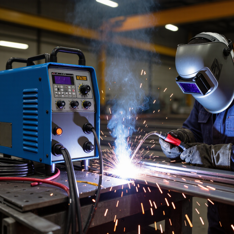
What Is a Welding Machine and How Does It Work?

What a Welding Machine Is and What It Does

A welding machine supplies and controls the electrical energy used to join metal. It sends current through a cable to an electrode or welding torch, while a separate clamp completes the circuit through the workpiece. When the process creates an arc, intense heat melts the metal edges. Filler material may be added to form the joint. The machine does not make every weld automatically; settings, materials, and operator technique all matter.

Different machines support different welding processes and power needs. Controls usually adjust output, such as current, to suit the metal thickness and electrode or wire being used. Too little energy can leave a weak, uneven joint. Too much may burn through thin sheet metal. A clean, tight connection also matters. It is easy to blame the machine for a poor bead, but preparation and steady movement can be just as important.

Tips: Check the machine’s manual and match its settings to the task. Wear a suitable welding helmet, gloves, and protective clothing, and keep sparks away from flammable materials. Inspect cables and clamps before use. Small setup details are easy to overlook, even by experienced users.

The Main Components of a Welding Machine

A welding machine contains several parts that work together to control electrical power and deliver it to the joint. Its power source changes incoming electricity into a form suitable for welding. In many modern machines, electronic components regulate current quickly and precisely. The selected current affects how deeply the arc melts the metal. Too little may produce a weak bond; too much can burn through thin sheet.

The control panel lets the operator set output, polarity, or process settings, depending on the machine. Cables carry current to the torch or electrode holder and return it through the work clamp. The clamp must grip clean metal firmly. A loose connection can cause unstable arcing, and it may be mistaken for a machine fault. Small details matter.

The torch or holder guides the electrode and directs the arc toward the joint. Some machines also include a wire feeder, gas connections, or cooling components. Fans and vents help remove heat from internal parts, so blocked vents can shorten service life. Keep them clear. The outer case protects electrical components from dust and impact, but it is not a substitute for inspection. Machine layouts vary, which can make troubleshooting less tidy than a diagram suggests. A practical check starts with cables, clamps, settings, and airflow before assuming the power source has failed.

How a Welding Machine Controls Electrical Power

A welding machine controls electrical power by converting mains input into a stable, adjustable output. In an inverter-based unit, rectifiers convert incoming alternating current to direct current; electronic switches then reshape it at high frequency. A transformer and output circuitry adjust voltage and current for the selected process. Feedback sensors monitor the arc, helping the machine respond when arc length changes. The AWS Welding Handbook describes constant-current output for processes such as manual electrode welding, and constant-voltage output for wire-feed welding. That distinction matters: the power source must suit the process, not just deliver more amperes. Small changes can affect the bead.

Controls set current or voltage, while some machines also coordinate wire-feed speed and arc response. IEC 60974-1 rates welding power sources by duty cycle over a 10-minute period. At a 60% rating, the source can deliver its rated output for six minutes, followed by four minutes without that load, within test conditions. Heat is controlled. In practice, ambient temperature, airflow, and cable condition can affect performance, so the rating is not a promise for every jobsite. One useful habit is checking the machine’s rating plate before a long weld; it is easy to overlook, and I would not assume the display tells the whole story. (Sources: AWS Welding Handbook; IEC 60974-1.)

What Is a Welding Machine and How Does It Work? - How a Welding Machine Controls Electrical Power

Stage or Control What the Machine Does Electrical Behavior Why It Matters in Welding
Input power Receives electricity from a compatible supply, such as single-phase or three-phase mains power, depending on the machine. The input voltage and frequency must match the machine’s rating. The power source draws electrical energy and converts it for welding. Using an unsuitable supply can prevent operation, reduce performance, or create an electrical hazard.
Power conversion Changes the incoming power into a form suitable for producing a controlled welding arc. Transformer-based machines reduce voltage and increase available current. Inverter machines use electronic switching, often at high frequency, to control power with smaller magnetic components. The conversion method affects machine size, weight, efficiency, and the way output is regulated.
Rectification and output Depending on the design, converts power to direct current (DC), or supplies alternating current (AC) for welding. Rectifiers convert AC to DC. Some machines can provide selectable AC, DC, or both; the available output depends on the machine and process. Output type influences arc behavior and which materials, electrodes, and welding processes are suitable.
Welding current setting Lets the operator set or adjust the welding current, usually measured in amperes. Many stick and TIG power sources regulate current (constant-current output). The selected current affects the arc and the heat delivered to the workpiece. Appropriate current depends on factors such as process, electrode or tungsten size, material, and joint conditions.
Voltage and arc control Maintains an output suited to the selected process and responds to changes during welding. MIG/MAG power sources commonly use constant-voltage output; arc length and wire-feed speed influence welding current. Stick and TIG machines commonly use constant-current output. Different processes need different output characteristics for a stable, controllable arc.
Polarity selection On machines that provide DC output, allows the welding leads to be connected for the required polarity. Common DC configurations are electrode positive (DCEP) and electrode negative (DCEN). The appropriate configuration depends on the electrode, wire, and process. Polarity affects arc characteristics and heat distribution; always follow the electrode or filler-metal guidance.
Wire-feed control On wire-feed systems, drives electrode wire toward the weld at a selected rate. Wire-feed speed is commonly measured in inches per minute or metres per minute. It is coordinated with voltage and other process settings. Correct coordination helps maintain a stable arc and consistent deposition in wire welding.
Duty cycle and thermal protection Limits operation time at high output and may stop or reduce output if internal components overheat. Duty cycle is usually stated as a percentage of a 10-minute period at a specified output. For example, 60% means welding for 6 minutes followed by 4 minutes of cooling under the stated test conditions. Exceeding the rated duty cycle can trigger thermal protection and interrupt welding; ratings vary by machine and output.

Note: Welding output, control options, and compatible input supplies vary by machine. Check the machine’s rating plate and operating manual before connecting or setting it up.

How the Welding Process Forms a Strong Joint

A strong weld starts with clean, closely fitted surfaces. Rust, oil, paint, or a wide gap can interfere with fusion. The welding machine supplies controlled electrical energy, creating heat that melts the edges of the metal. The puddle is small, but its temperature is high. Steady hands matter.

As the torch or electrode moves along the joint, molten base metal combines with filler metal when the process requires it. The weld pool cools behind the arc and solidifies into a continuous connection. Shielding gas or flux helps protect the hot metal from air, which can otherwise contribute to porosity or a brittle weld. Heat, travel speed, and electrode angle all affect the finished joint. Small changes matter.

Strength depends on more than appearance. A smooth bead may conceal poor penetration, while excessive heat can distort thin sheet metal. That trade-off is easy to underestimate. Good preparation, suitable settings, and consistent movement help produce reliable fusion, but the right choices vary with material thickness and joint design. After cooling, the weld should be checked for visible cracks, gaps, or uneven areas; critical work may need additional inspection. A tidy surface is useful evidence, not proof by itself.

Common Types of Welding Machines and Their Uses

A welding machine supplies controlled electrical power to create an arc, which melts metal edges and joins them as they cool. Different machines suit different materials, positions, and workspaces. The process matters as much as the machine.

MIG machines feed wire continuously, making them practical for shop fabrication, steel frames, and longer welds. They are relatively easy to learn, though wind can disturb their shielding gas outdoors. TIG machines use a separate tungsten electrode and offer careful control for thin stainless steel or aluminum. The pace is slower. Stick machines use replaceable coated electrodes and handle outdoor repairs well, especially on thicker steel, but produce more spatter and require slag removal. Inverter power sources are compact and efficient; many support several processes, depending on their settings and accessories.

Tips: Match the machine’s output to the metal thickness and process. Check the duty cycle before long welds; a small machine may need cooling breaks. Clean rust, paint, and oil from the joint, then test settings on scrap. A tidy bead can still hide poor fusion, so inspect the joint rather than judging appearance alone. Wear suitable eye and skin protection, and follow the machine’s operating instructions.

Common Welding Machine Types and Typical Output Current

The bars show indicative output-current ranges in amperes for common SMAW (stick), GMAW (MIG), GTAW (TIG), and SAW machines. Actual ranges vary by machine, process, material, and duty cycle.