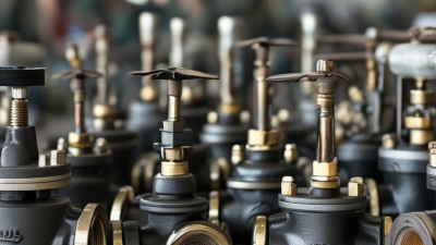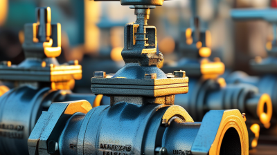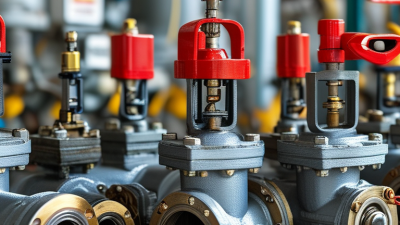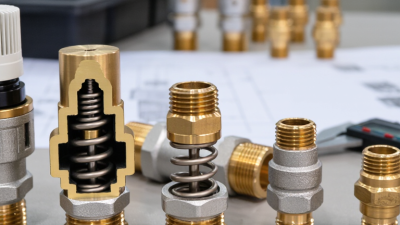
A Relief Valve is a mechanical safeguard that protects equipment from dangerous overpressure. It opens when system pressure reaches a defined set point. Then, it releases fluid until pressure returns to a safer range. Think of a spring-loaded valve lifting from its seat while steam, gas, or liquid escapes through the outlet.
This function appears simple. The engineering is not. Valve selection depends on pressure, temperature, fluid properties, discharge capacity, and backpressure. API 520 provides guidance for sizing and selecting pressure-relief devices. API 521 addresses pressure-relieving and depressuring systems, including discharge routing and flare-system considerations. ISO 4126-1 also establishes requirements for safety valves. These standards show why a relief device cannot be chosen by pipe size alone.
Industry data reinforces the need for disciplined protection. Grand View Research’s Industrial Valves Market report identifies growing demand for valves across energy, chemical processing, water, and manufacturing applications. However, market growth does not guarantee safe installation. U.S. Chemical Safety Board investigation reports have repeatedly highlighted the consequences of weak pressure-control practices and inadequate hazard reviews. Small errors matter.
A blocked outlet can defeat protection. Incorrect set pressure can delay opening. Poor maintenance can leave the valve stuck. This article explains how a Relief Valve works, where it fits within a pressure-protection system, and which details engineers verify during selection and inspection. The explanation is intentionally practical, although real systems can be less tidy than diagrams suggest. Experience still matters. Specifications must be checked against the actual process.
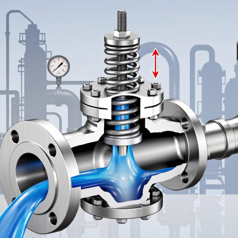
A relief valve is a mechanical safety device that releases excess pressure from a vessel, pipe, or process line. It protects equipment when pressure rises beyond a permitted limit. The valve usually remains closed under normal conditions. A spring, pilot mechanism, or weighted element holds it shut.
The phrase “10% overpressure” needs careful interpretation. In many systems, the valve is set to open at a defined pressure, then reaches full capacity within an allowable overpressure, often 10% above that setting. For example, a valve set at 100 bar may relieve its rated flow by 110 bar. This limit is not universal. System design, fluid type, temperature, and applicable engineering standards can change it.
During commissioning, technicians verify the set pressure, discharge path, and valve response. A pressure gauge may rise slowly, then show a sharp drop when the valve opens. That moment matters. A blocked outlet, corroded spring, or incorrect adjustment can prevent reliable relief. Small errors become dangerous.
Regular inspection remains essential. A valve can look clean while its seat has weakened. Testing should follow the equipment maker’s instructions and relevant safety requirements. In practice, pressure protection is not only about the valve itself. It also depends on correct sizing, stable installation, and a discharge route that can safely handle the released fluid.
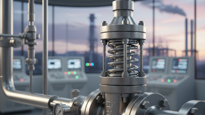
A relief valve protects equipment when internal pressure rises beyond a safe limit. Its spring, disc, nozzle, and set-pressure mechanism work as one compact system. The spring presses the disc tightly against the nozzle seat. This keeps the vessel sealed during normal operation. When pressure reaches the set point, the disc lifts. Fluid then escapes through the nozzle, reducing pressure before damage occurs.
The spring controls the opening force. Adjusting its compression changes the set pressure, but temperature and back pressure can shift performance. The disc must resist corrosion and maintain a reliable seal. The nozzle directs flow and determines part of the valve’s discharge capacity. API Standard 520, Part I, uses relieving pressure, temperature, and fluid properties for sizing. ASME BPVC Section VIII also requires pressure-relief protection for many pressure vessels.
The IEA Energy Efficiency 2024 report states that industry consumes nearly 40% of global final energy. Many industrial systems therefore operate continuously under demanding conditions. A small setting error can become a serious process risk. Field inspections often reveal blocked outlets, damaged seats, or incorrect spring adjustments.
The valve may look simple.
Technicians should verify the nameplate, set pressure, discharge route, and maintenance history. A useful check is comparing the installed valve with the latest process data. That step is sometimes missed.
A relief valve protects pressurized equipment from excessive internal pressure. In a spring-loaded design, a spring holds the valve closed against a seat. The spring force matches the valve’s set pressure. When system pressure rises above that point, the fluid force becomes stronger than the spring force. The disc lifts from the seat, creating an opening.
The opening may look small at first. It can grow as pressure continues to increase. Fluid then escapes through the outlet, reducing pressure inside the vessel, pipe, or process line. During field inspections, technicians often watch for vibration, unusual noise, or a visible discharge plume. These signs can indicate unstable flow, incorrect sizing, or a valve opening too frequently. Small errors matter.
Once pressure falls below the reseating level, the spring pushes the disc back toward the seat. The valve closes when contact is restored, stopping the discharge. Resealing is not always perfectly clean. Dirt, corrosion, or a damaged seat can leave a small leak after closure. A pressure gauge may show recovery, but that alone does not prove a tight seal. Testing should confirm opening pressure, discharge behavior, and resealing performance under controlled conditions. One practical lesson is easy to miss: a valve that never opens may still be unsafe if its set pressure is wrong or its outlet is blocked.
A relief valve opens when system pressure reaches its set pressure. Its real job is more specific: it must discharge enough fluid to prevent unsafe overpressure. API 520, Part I, separates sizing methods for gases, steam, and liquids. Each method uses relieving pressure, temperature, compressibility, density, and required flow rate. The required capacity comes from the credible upset case, such as blocked discharge, fire exposure, or thermal expansion. Set pressure alone is not enough.
Backpressure can quietly reduce valve capacity. API 520 distinguishes superimposed and built-up backpressure, while API 521 provides guidance for identifying relief scenarios and disposal-system effects. Conventional valves may lose performance when backpressure rises. Balanced designs can reduce that influence, but they still require a verified correction factor. ASME BPVC Section VIII also links pressure-relief protection with certified capacity. A tidy spreadsheet can still hide a bad assumption. Recheck the fluid phase at relieving conditions.
Tips: Start with the worst credible case, not the normal operating rate. Use certified coefficient data and the correct discharge coefficient. Confirm inlet pressure loss, outlet piping, reaction forces, and flare-system pressure. For liquids, calculate viscosity effects carefully. For gases, check molecular weight and compressibility. Field conditions rarely match the ideal model perfectly. That gap deserves engineering judgment.
A relief valve is a mechanical safeguard against excessive pressure. When vessel pressure reaches the set pressure, spring force is overcome. The valve lifts and releases fluid through a controlled outlet. It reseats after pressure falls. The principle is simple. Proper protection is not.
ASME BPVC Section VIII, Division 1, UG-125 requires pressure vessels to have suitable overpressure protection. Typical accumulation limits are 10 percent for one device and 16 percent for multiple devices. Fire exposure may allow 21 percent under specific code conditions. These limits must match the vessel’s maximum allowable working pressure, or MAWP. ASME also addresses certified relieving capacity under UG-131. Engineers should verify actual service conditions, not only copy previous calculations.
API 526 standardizes flanged steel relief valves and interchangeable orifice designations. Its D-through-T series contains 14 effective-area sizes, ranging from 0.110 to 26.0 square inches. This consistency supports faster selection and clearer procurement data. However, API 526 does not replace process sizing. API 520 methods require relieving pressure, temperature, fluid properties, and certified coefficients. In field commissioning, blocked outlets, built-up backpressure, and fouling can undermine clean calculations. A neat spreadsheet can still hide an undersized discharge line. Reviewing assumptions twice feels inefficient, yet it often prevents costly surprises. These technical figures reference ASME BPVC Section VIII and API 520 and 526 publications.